This could be considered a nostalgia machine, a old CRT that has been upgraded with internet capabilities
which enables viewing of cartoons from years past. Specifically the TV show from 1967: Spiderman (in color!)
A quick note: A CRT is an old TV that uses cathode ray tubes to project an image through a vacuum. IoT stands
for Internet of Things and basically means giving internet/network capabilities to devices that otherwise
could not.
I was given a Raspberry Pi from my father many years ago and I didn't have a clue what to make with it. I knew
what it was and that there was a whole community around it, but I just couldn't think of anything. It's ironic
that this device basically had endless possibilities yet it sat in my desk drawer for years. Covid hit and
everyone was stuck at home and on video calls. This is when an idea finally manifested in my head; a CRT that
continuously loops old cartoons! There shouldn't be any need to press the power, change the channel, etc. Just
plug and watch. It could be placed in the background as kind of a piece of art. Sadly the project was shelved
when my computer couldn't create an 8hr video file of old looney toons.
Later the RPi was turned into a server so the CRT project was put even deeper into the shelf. Whilst at work I was
learning some bash scripting and it occured to me that I could use bash to loop through many smaller videos
rather than trying to make a single, very long video. Now I needed some more pi. Because of the chip shortage,
the prices of microprocessors were astronomical. They were out of stock from the retailer and heavily marked
up on the second-hand market. I finally found some gen 1 Pi in Toronto. The seller happily mailed them to me
and thus the project was afoot.
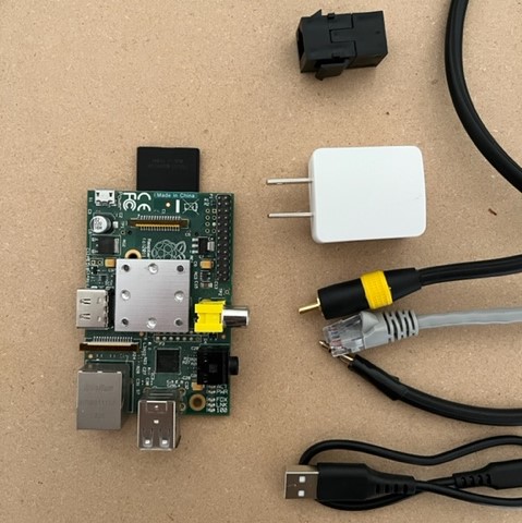
First, the CRT needs a microprocessor. Secondly most CRTs only communicate via Component cables so I need a set of those.
Third, the pi needs an external memory device and power. Fourth, the microprocessor needs to be programmed.
Each part was not trivial to obtain.
CRT- This was actually the last device to obtain because an external monitor could substitute for awhile.
Second-hand marketplaces had a few but they were marked up because the seller thought they were worth even $20.
There was almost a deal for $15 but the seller backed out at the last minute to because apparently his son wanted
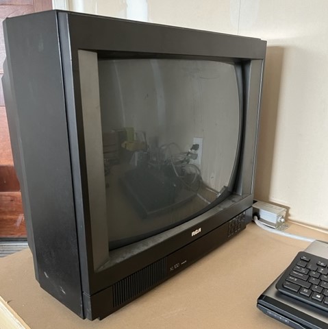
it. Eventually a free one was found and picked up near the end of the project (see thumbnail).
Component Cables- Also a marketplace buy, this time easier and cheap. There was a glaring issue with the cables
however...
External Memory- The original pi only takes a SD card, not a micro SD, just a SD. Many marketplace sellers seemed
sketchy, as if they bought them in bulk from Alibaba and were upselling them here. Anyway it was a much safer option just
to go to
The Source
HDMI cables are neat. tidy, and consistent. However they are also new-
ish. This means that CRTs do not have an HDMI
port, only component ports. An option would be to convert from HDMI to component but but but this would mean buying an
adapter. It is non-trivial to DIY an adapter because HDMI does not send data in the same way a component cable does. This
DIY would involve adding a microcontroller to the mix and coding the conversion. A more simple approach would be to just use
component cables. The RPi has a component video output but no component audio out. Instead it has a 3.5mm port (headphone jack). Therefore
the headphone cable needs to be converted to component. These two types of cables both work the same on a basic level so it
can be done.
Both cables are coaxial cables. This means that there is a data cable in the middle with a ground sheath wrapped around it. Thats
it for components but headphones have more than one data cable.
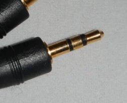
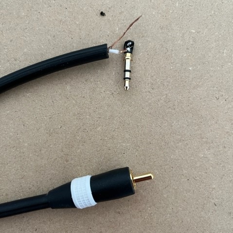
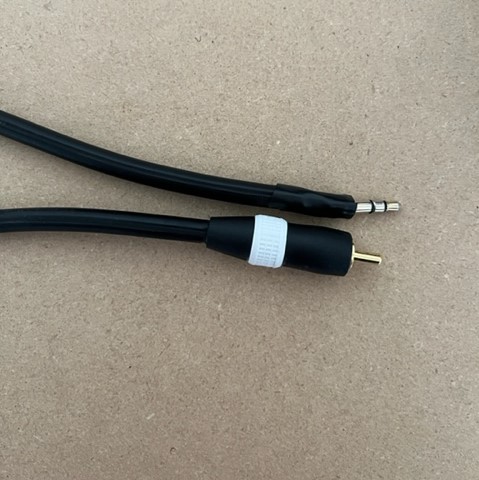
The black bands on the jack are insulators that separate the serial data. Typically the ground is nearest to the base and then
it goes: left audio, right audio, microphone. If the jack only has 2 bands (and thus 3 seperate serial streams) then there is most
likely no microphone. Furthermore if there is only one band then it is just mono-audio. The headphone cable that will be used has
two bands but since component cables only have one data stream, the two audio sections can be combined. The RPi 3.5mm port supports
four bands and since we will only use the ground and mono-audio, it will work fine.
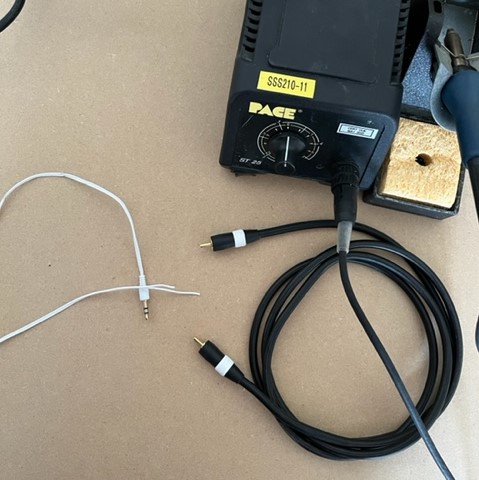
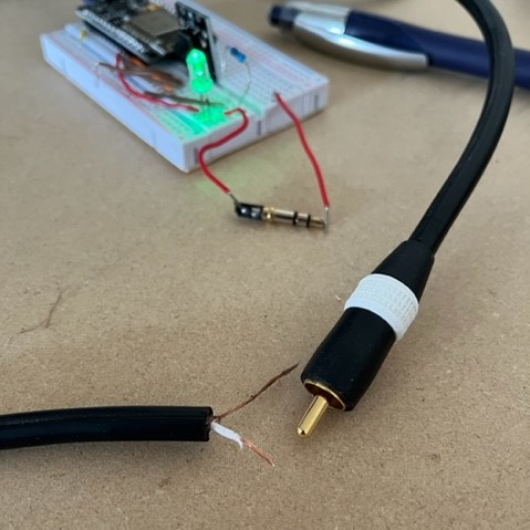
For this DIY soldering was a great option. This required a soldering iron, solder, wire snips, and electrical tape. The soldering
iron and snips were borrowed from work and the others were purchased. The plan was to cut both cables open and connect the two cables
however it turns out the headphone cables are of very high gauge. There were only about one or two copper strands in each sheath. This led to
tearing apart the actual connector which revealed quite a bit more soldering real estate.
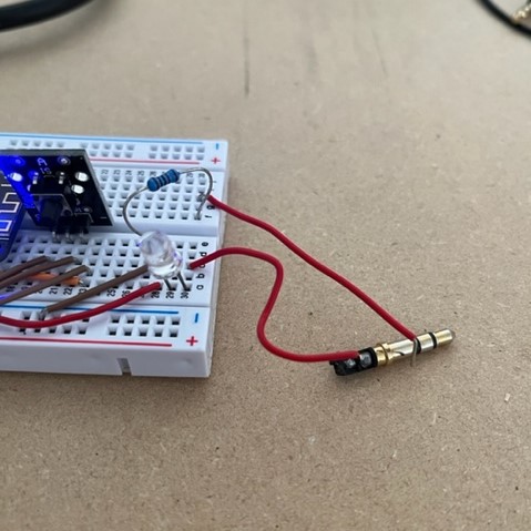
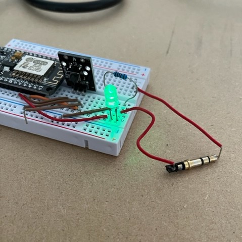
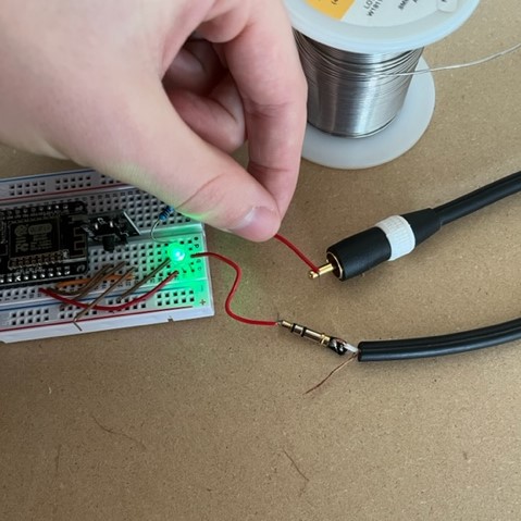
The connector had insulation around the base so it wasn't possible to tell how the jack was connected just by looking. The best tool
for the job would've been a multimeter to test the continuity... but I do not own one. The second best(?) tool was a LED in a circuit.
Insert the connector to the circuit and if the LED turns on, they are connected.
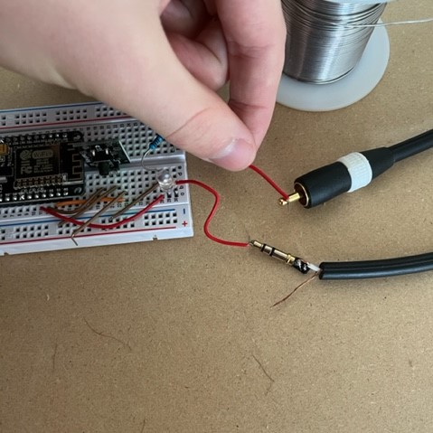
Once the 3.5mm connector was defined, it was on to the component cable. After cutting this open, the grounding sheath was twisted into a
wire and the inner material was stripped as well. Now the inner wires needed to be soldered to the mono-audio part and the sheath needed
to be soldered to the grounding part of the 3.5mm jack.
After the data cable was soldered it needed to be wrapped in electrical tape. This is because if the grounding sheath was just soldered at
the same time, there would be a high chance of the two wires touching and causing a short. The first solder was tested using the same
ad-hoc continuity tester as before.
It worked! The electrical tape was added and the grounding sheath was soldered.
Not bad. Now the RPi could be connected to both video and audio of the CRT.
The software has three pieces: a directory of videos, a script to play the videos randomly, and another script to start the first script on boot-up.
The videos were obtained on an archive website of old content and transferred to the pi via Filezilla. It was at this moment disaster struck.
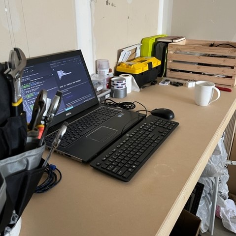
The wife got sick of looking at a TV and RPi in the living room and moved everything out to the garage. Fine. An old laptop was dug up from storage
and became
The WorkStation. This workstation was not good, but it was not its fault. It was an old computer trying to run the newest version
of Windows. The computer was installed with Linux Mint and it worked like new! The workstation has a leg up on the RPi because it has wifi capabilities.
The wifi router was in the basement and the project was in the garage. There was thought of stringing an ethernet cable through the drywall but I have already
done enough drywall damage to my house as is. The second option was to get a wireless access point, or better yet, turn the workstation into a wireless access
point. In the ethernet settings of the workstation, the
share with other computers option was enabled for ipv4 settings. Secondly the IP of the WorkStation
was added as a DNS server for the RPi. Boom now the RPi has the internet. Back to the code.
The code is not too complex, however this was my first attempt at bash so it was a great learning experience. First is the randomly looping video script. The
first thing is to check if a video is running, if it is then wait and check again in a second. If a video isn't playing then pick a random video and play it. The random number was
generated by
i=0
rand=$[$RANDOM%77+1]
This will generate a random number between 1 and 77 (the number of video files). Next is the loop:
for entry in $VPATH/*
do
if [[ $rand -eq $i ]]
then
clear
omxplayer -r $entry > /dev/null
fi
((i++))
This loops through every file in the directory and if the random number is equal to the index of the video then it will play it.
This code is all wrapped in a while true loop which will loop the random videos forever. This file needs to be given executable permissions with chmod 755.
The autostart file is placed in the /etc/init.d directory and only has two lines of code:
/home/crt/randloop.sh
esac
This will start the random loop file and then escape so the rest of the boot can happen. This file too needs the executable permissions. Finally the rc.d file needs to be
updated to run autostart on boot up with update-rc.d autostart defaults.
Yes! And it randomly loops through the videos and autostarts. Last part is to take all of the pieces and put it into the CRT...
problem
Turns out the CRT I have doesn't even have component ports, only a cable input, I was looking at so many on the marketplace that I guess I got confused. Anyway the project works and the pieces
will be waiting until they have a screen. This may be a good time to reconsider what type of screen is best. CRTs are old which also means they draw a ton of power which is
not good for the bills. Secondly people are really only getting rid of large CRTs which are heavy and don't fit on a desk nicely. The ideal screen may actually be a tiny LED
screen...
Until then these parts will be waiting
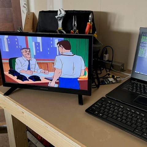
May 3 2022, the day has come:
Tinytoons!